
Beyond PCB Repair: Using BoardMaster as an Integrated Aerospace Test Development Platform
In aviation MRO, electronic troubleshooting rarely stops at the circuit board. The deeper challenge is often reproducing the conditions under which an avionics or engine-control assembly operates, developing reliable test equipment around it, and maintaining that test capability for decades. A recent aerospace MRO application demonstrates just how far an integrated diagnostic platform can be taken in the right hands.
The engineering team maintains Electronic Engine Controllers (EECs) used to control jet engines. These controllers must interpret numerous sensor inputs, including temperature measurements associated with areas such as the engine inlet, combustion section and exhaust. Thermocouples are widely used for this type of temperature measurement because they generate small electrical voltages related to the temperature difference between their measuring and reference junctions. Accurate thermocouple measurement therefore also requires consideration of the reference junction through Cold Junction Compensation (CJC).

Recreating an Aircraft Sensor on the Test Bench
Testing an EEC away from the aircraft creates an obvious problem: the controller still needs to receive realistic sensor signals. ABI’s customer solution is a purpose-built, multi-channel thermocouple simulator PCB that has formed part of its EEC test equipment for many years. Rather than physically heating sensors to different temperatures, the PCB generates the extremely small and highly accurate voltages that the EEC would normally receive from real thermocouples.
This principle is well established in instrumentation. Thermocouple simulation allows a known electrical representation of temperature to be injected directly into a controller so that engineers can confirm whether the receiving system responds correctly. The aerospace simulator takes this considerably further. Its firmware supports multiple thermocouple types, individual channels, calibration functions, stored calibration values and an onboard temperature sensor for CJC. Outputs extend into the microvolt range, where accuracy becomes critical. The latest engineering work is focused on improving the simulator firmware and investigating its behaviour in much greater depth.
BoardMaster Becomes the Development Bench
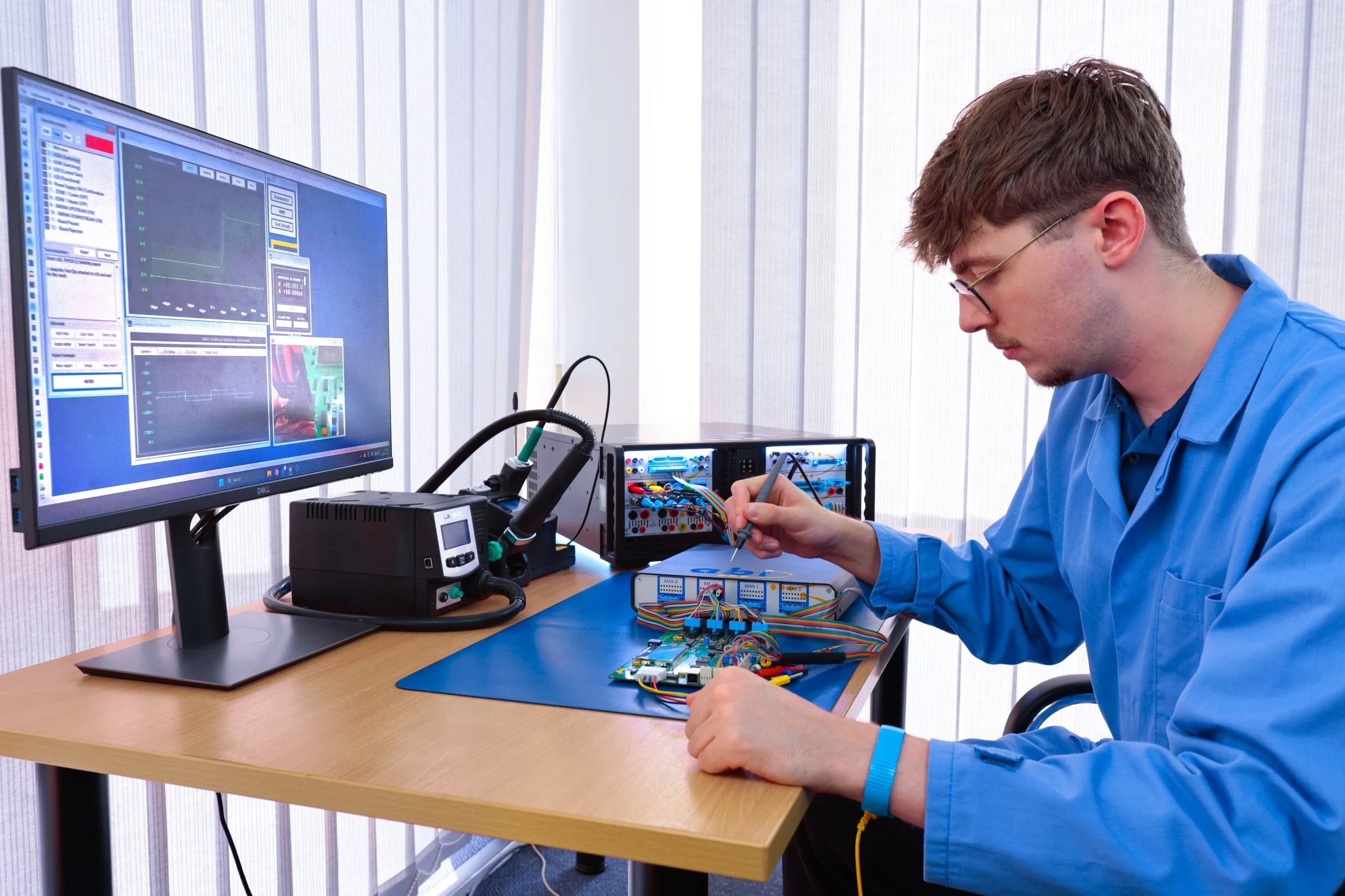
Instead of assembling a collection of independent instruments around the simulator, the engineer uses the ABI BoardMaster as the central development platform. BoardMaster’s wider architecture brings together programmable power, oscilloscope, voltmeter, ohmmeter, arbitrary waveform generation, frequency/event counting, programmable I/O, analogue and digital functional testing and powered and unpowered diagnostic methods within one platform. The integrated Programmable Power Supply provides the multiple power rails needed by the simulator. This is particularly useful when an embedded design contains different digital, analogue and interface supply requirements.
The Digital Storage Oscilloscope (DSO) is then used during firmware debugging. Spare microcontroller outputs can be deliberately toggled from software and probed with the oscilloscope, allowing the engineer to observe when particular firmware functions execute and investigate potential timing problems. The DSO therefore becomes a window into the interaction between firmware and hardware rather than simply being used to look for a waveform on a failed PCB.
The BoardMaster voltmeter is also used to provide a convenient indication that the simulator’s low-voltage outputs are responding. For the final microvolt-level calibration, however, dedicated precision metrology remains necessary. This is good engineering practice: use each instrument for the job its accuracy and specification are designed to perform.
One Platform, Very Different Aerospace Problems
What makes this application particularly interesting is how different it is from another recently documented FADEC repair challenge. In that application, an aircraft’s onboard diagnostics identified an RTD-related fault within a FADEC. The circuit contained 42 precision resistors with 0.1% tolerance requirements. The traditional process involved measuring components individually, comparing results with a known-good assembly and recording results manually. The MRO team instead developed a BoardMaster TestFlow using structured measurements, the MIS4 Ohmmeter, visual instructions, tolerances and reporting. The resulting procedure reduced the RTD test stage by more than 50% while improving repeatability and traceability.
The two applications illustrate completely different uses of the same platform. One uses BoardMaster to turn a repetitive FADEC diagnostic procedure into a controlled, software-led workflow. The other uses BoardMaster interactively as an embedded-development and aerospace test-bench engineering tool.
A Mobile Engineering Laboratory
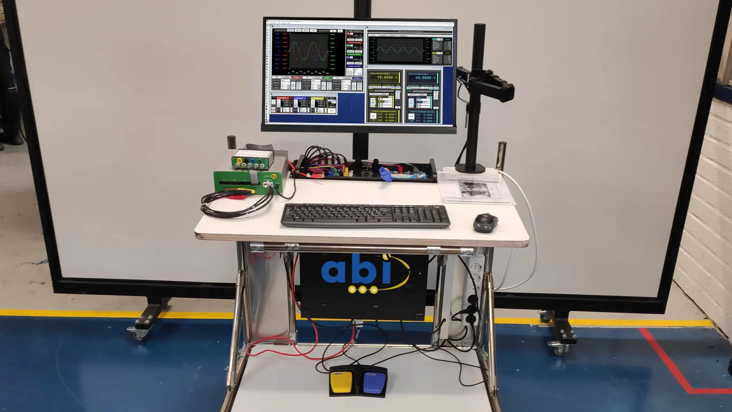
The ABI MRO customer has taken the concept another step by mounting the complete BoardMaster installation vertically beneath a purpose-built mobile workstation. The monitor, interfaces, cabling and supporting equipment travel together, allowing engineers to wheel the complete test capability between repair benches. That matters in an MRO environment. Expensive instrumentation does not have to become permanently tied to one workstation or one application. The same integrated platform can support PCB diagnosis, analogue measurements, digital investigation, firmware development, test-equipment troubleshooting and engineering experimentation according to the job in front of the technician.
BoardMaster provides the instruments and diagnostic methods, but engineering knowledge determines how far those capabilities can be taken. Its established applications include Power ON and Power OFF diagnostics, V-I analysis, analogue and digital functional testing, live comparison, automated TestFlow procedures and support for FADEC-related and ground-test electronics. Put those capabilities in the hands of an engineer who understands the circuit, the software and the system being maintained, and BoardMaster stops being simply a PCB troubleshooting machine. It becomes an engineering platform for solving whatever electronic problem arrives at the MRO bench next.